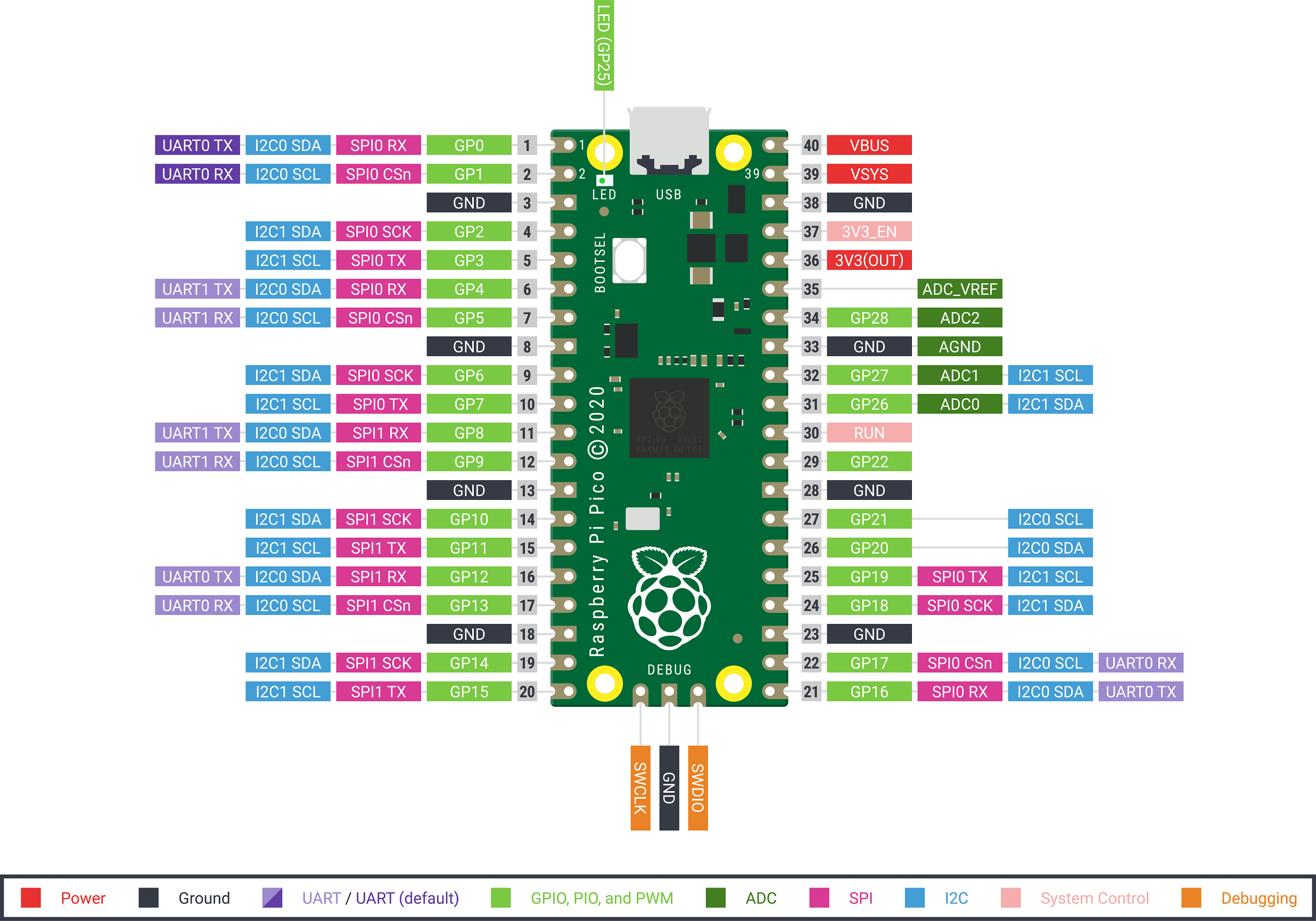


Thanks I think this is what you are referring to also, as well as p0 through p29. I will just point to '4' rather than GP4 in the digitalwrite statement now and see if that works, as it should as you have indicated.

Which is why I was asking the question of what term I need to use. When I was playing around yesterday, doing setting say GP4 to output, and then setting it high and low, did not do anything. I just was not sure how to pinpoint the pin I want to operate as I could not find a reference anywhere. Yes, very aware of physical vs software differences here. Sorry I mistyped in my original post, RE say Pin 4 is GP4. I already have a working demo here running with Serial1, as Serial did not work. Yes I realise it states UART0 on the pin diagram, but that is what I tried first and it doesn't match in reality. Thanks but 'Serial1' is what appears to make Pin1 and Pin2 operate as a Serial UART. Note here how there are no default pins for I2C bus 1, if you use that bus you have to specify them. The same goes for the two I2C buses, pins 4 & 5 are the default pins for I2C bus 0, with alternate pins meaning you have to specify them. Using the faded colour alternative pins means to need to specify the pins you want to use. Note how pins 0 & 1 are a stronger shade of the colours on the other pins, this indicates that these are the default pins. So you will see you can have serial communication coming from pins 0 & 1 or 16 & 17 or 16 & 17. Other boxes are alternative uses for the pin number. The Green boxes containing the GP0 numbers are what you should use in your code and are the same as Arduino Pin numbers. Also where as you can have a pin 0 in software, you can't have a pin 0 as a physical pin. For example the Uno has no simple physical scheme numbering you can follow. Perhaps the only use is in wiring diagrams, but again is rarely used in the Arduino world ether mainly because different versions of the Arduino have different physical forms. Otherwise yes:- the 1 in the grey box is the physical pin number and as such is something you never refer to in code. Well first off it is not used with Serial1 but with Serial0 as the label says. Pin1 is the UART0 TX, which is used with Serial1 it seems, and is labelled GP0.


 0 kommentar(er)
